
Ground Penetrating Radar (GPR) is a research technique used in shallow geophysical applications, boasting a very wide range of uses. Subsurface structures are examined with high resolution through radargrams—generated by transmitting high-frequency electromagnetic radar signals (between 10 MHz and 3 GHz) into the ground via a transmitting antenna and analyzing the round-trip travel times of the resulting subsurface reflections (Figure 1).

Figure 1: A simplified illustration showing the propagation of radar waves—emitted from a transmitting antenna—through the subsurface and their arrival at a receiving antenna, along with the representation of the acquired A-scan data as B-scans and C-scans. https://geoim.net/radarteam-gpr/
Electromagnetic waves are transmitted into the subsurface at specific center frequencies; the source frequency plays a critical role in the depth of penetration, scattering, and absorption of the radar waves as they propagate through the medium. Furthermore, the dielectric permittivity, electrical conductivity, and magnetic permeability of subsurface materials significantly influence the wave fields traveling underground. Given these factors, the nature of the ground-penetrating radar (GPR) method is complex; interpretation challenges arise, particularly when considering that the subsurface is often highly heterogeneous. In this context, both the theory governing electromagnetic wave propagation and the principles of geometric optics are of great importance. The dielectric properties of each material or medium of subsurface are significant; by treating each as an electrically insulating medium, one can attempt to characterize the subsurface based on these properties. Naturally, electrical conductivity and magnetic permeability are also key factors and are accounted for when solving the relevant mathematical equations. Optical theory is particularly relevant when the subsurface medium is dry. If the materials contain water or moisture, thedielectric state of the medium becomes a crucial factor in wave transmission (Table 1).
Table 1. Relative dielectric permittivity coefficient, electrical conductivity σ, and attenuation α values of different subsurface environments (adapted from Daniels, 2004)
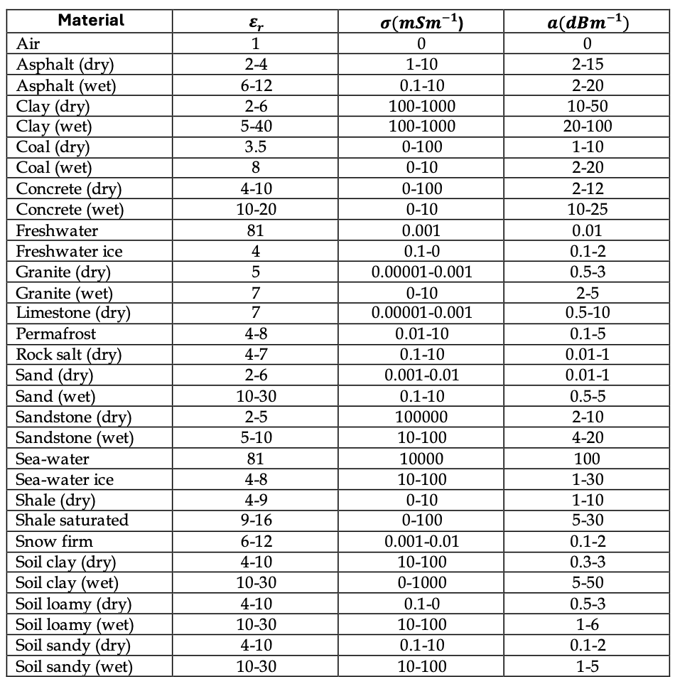
Table 2. Application areas of the Ground Penetrating Radar (GPR) method
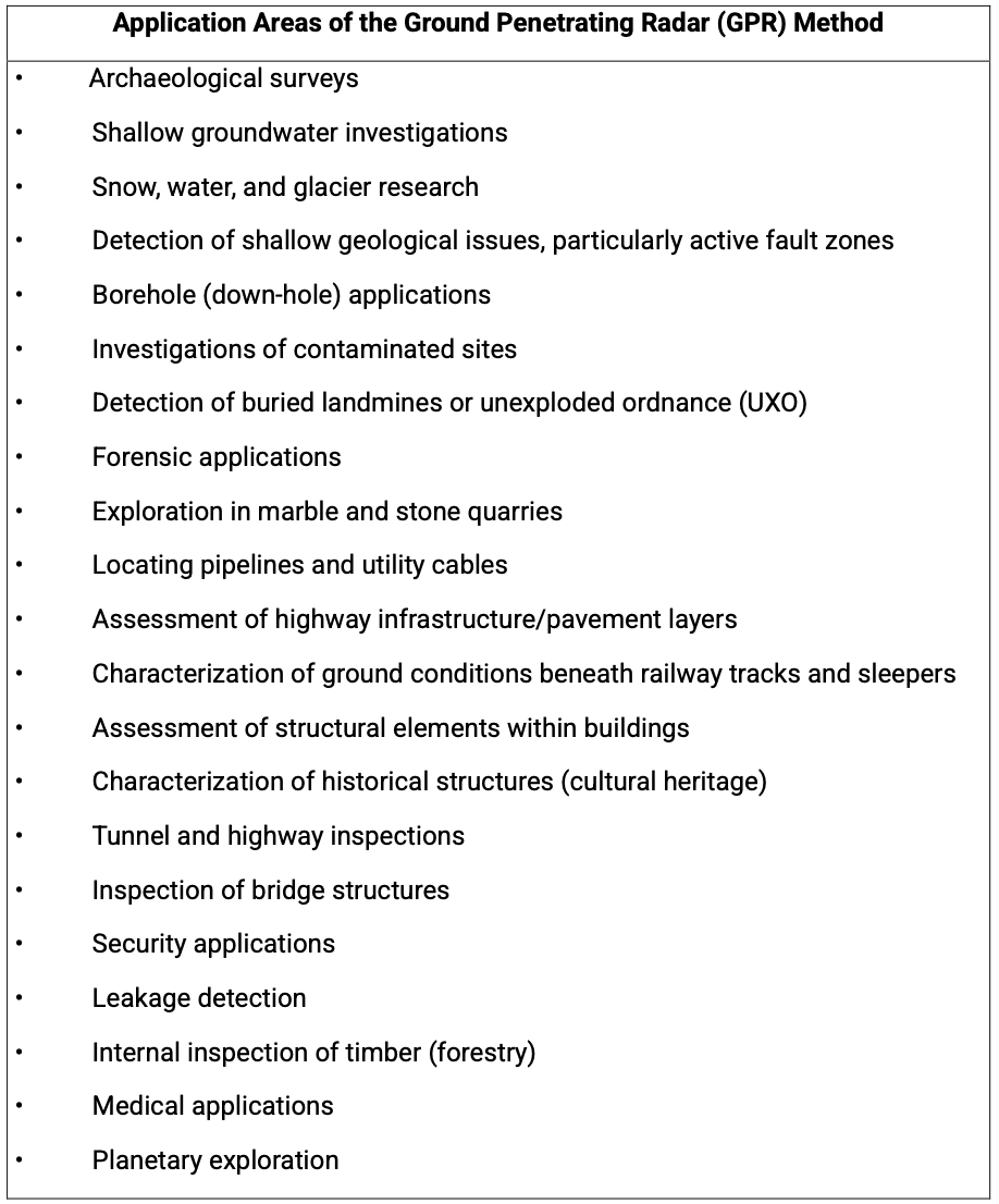
Today, this method has a wide range of applications and is used to address almost all types of shallow geophysical problems. It has a wide range of applications, particularly in areas such as shallow geological investigations (stratigraphy, fault identification, landslides, karst cavities, shallow groundwater aquifer studies, etc.), the examination of archaeological structures and living cultural heritage, engineering projects (pipeline surveys, investigations for tunnels, highways, and railways, assessment of building infrastructure and internal structural issues, etc.), the detection of unexploded ordnance and landmines, forensic science, the study of natural disasters, the identification of pollution and underground chemical fluid leaks, research on solid waste disposal sites, mineral deposit detection and ore exploration, as well as marble quarrying (Table 2) (Klein and Santamarina, 2003; Huisman et al., 2003; Lucius et al., 1992; Bristow et al., 2000; Drahor, 2007; Drahor et al., 2011).
Antennas commonly used today for transmitting signals into the subsurface are “ground-coupled”—meaning they must be in direct contact with the ground to take measurements. This reliance on ground contact creates several drawbacks. In areas with uneven or compromised terrain, taking measurements with such antennas is often impossible; furthermore, surface features—such as rocks, irregularities, or abrupt topographical changes—can interfere with the antenna, introducing unwanted artifacts like “ringing” into the data. While some of these issues can be mitigated through signal processing, others remain, resulting in problematic or unreliable recordings.
To address these challenges, “air-coupled” antennas have been developed. Leveraging recent technological advancements, these systems operate wirelessly, transmitting signals into the ground and recording the reflections that return to the antenna. This approach not only simplifies the measurement process but also minimizes interference—such as background noise from cables, ringing effects, and fluctuations in signal amplitude—that often plague ground-coupled systems. In contrast, ground-coupled systems are highly susceptible to these factors, leading to more frequent issues in the recorded data. Moreover, these modern systems are designed for versatile deployment: they can be mounted on vehicles, carried by hand, transported via push-carts, operated from the air (using drones or helicopters), or even used on freshwater lakes from a boat (Figure 2). Thus, with the aid of these devices—which allow for flexible use and data collection with less equipment—it has become possible to examine greater depths (up to a maximum of 125 m) and to investigate a wide variety of different issues more effectively.
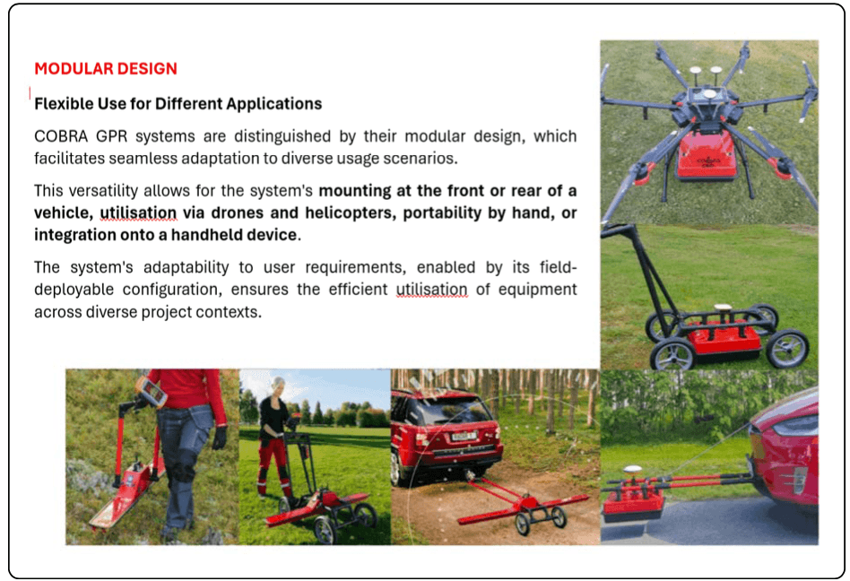
Figure 2: A new class of ground-penetrating radar (GPR) systems with modular designs
https://geoim.net/radarteam-gpr/
Furthermore, in recent years, dual-frequency antennas have emerged as an alternative to traditional monostatic single-frequency antennas, enabling simultaneous measurements across two distinct frequencies. In these systems, however, data are collected separately and then combined for interpretation following two independent evaluations. Figure 3 presents a comparison of three types of antennas. Single-frequency antennas rely on a central frequency and examine the subsurface in the context of frequencies associated with that central frequency. As shown in the figure, a 400 MHz antenna—commonly used in practical applications—operates within an effective frequency range of 200–600 MHz. Such an antenna can only detect buried objects within the limits defined by its specific frequency band. Consequently, to investigate objects of varying depths and sizes, antennas with different frequencies must be employed in the same area. Thus, using multiple antennas in the same location is essential for accurately determining the position, depth, and dimensions of a subsurface object.
Dual-frequency antennas, by contrast, operate using two independent frequencies. They effectively capture two separate datasets—each corresponding to a different frequency—in a single measurement pass, thereby reducing the time required for data acquisition. In terms of frequency content, for instance, if signals are transmitted at 600 MHz and 300 MHz, the system can simultaneously examine ranges of 300–900 MHz (associated with the 600 MHz signal) and 150–450 MHz (associated with the 300 MHz signal). However, since these antennas take two independent measurements, a “dead zone” emerges between the two frequency bands. Data falling within this range—for instance, the 300–600 MHz interval in this example—fails to form a complete radar pattern, and data around 450 MHz does not behave in a reliable manner. Consequently, when merging radargrams, there is a high probability that problematic signals originating from these zones will be included.
In contrast, multi-frequency antennas—such as the COBRA CBD GPR system—collect continuous data across the 200, 400, and 800 MHz bands. By accurately integrating these into a single radargram, the subsurface can be investigated using a signal range of 50–1400 MHz. This allows for in-depth analysis within a single recording, free from artificial signal discontinuities or system-induced amplitude attenuation (beyond what is naturally caused by the medium itself). An examination of the frequency spectrum for such a system clearly reveals the effective ranges of the three distinct frequencies, with no significant variations—other than approximately 2–3 dB—observed in the overlapping regions. Thus, this class of antenna can scan the subsurface across the specified frequency ranges, yielding results for all depths. Provided that the electrical conditions of the subsurface are favourable, such a system enables continuous, high-resolution investigation of the ground down to a maximum depth of 12 meters. The general advantages of these antennas can be summarized as follows:
- Data is blended/integrated into a single file, with the optimal frequency automatically selected for each depth.
- High-resolution/high-frequency data for near-surface targets, and lower-frequency data for deeper targets.
- No need to adjust frequency filters; the intelligent CBD (Continuous Bandwidth Dipole) antenna performs its own filtering.
- No “dead zones” or blind spots in the data, thanks to blended frequencies.
- Direct velocity calculation derived from frequency content using a proprietary formula.
- Option for Real-Time Sampling technology.
- Air-coupled operation without “ringing.” (Other antennas typically require direct contact with the ground to prevent ringing—a condition that is not always feasible during measurements.)
Such a system offers researchers an unparalleled investigative capability, featuring a CBD antenna with a unique 1350 MHz bandwidth and a wide array of advantages. With its advanced design—capable of replacing multiple GPR antennas that have nominal frequencies ranging from 200 to 800 MHz—the CBD technique represents a state-of-the-art solution for GPR surveys.

Figure 3: Comparison of Ground Penetrating Radar (GPR) antenna systems
https://geoim.net/radarteam-gpr/